Background
Recently, I became fascinated by a concept I was introduced to by the (ever benevolent, omniscient) Youtube algorithm: mirrorball projections.
https://www.youtube.com/watch?v=rJPKTCdk-WI
Apologies for the sort of gross thumbnail preview, but I really do recommend watching the video. I will nonetheless summarize the aspects that most captivated my attention.
Somewhat counterintuitively, the image of a mirrorball, which of course can only ever be observed as a mirror-hemisphere, captures a complete 360-degree image of the surrounding space, from the perspective of the mirrorball, excluding the exact shadow of the mirrorball from the perspective of the camera. I say that this is sort of counterintuitive because one might expect that the mirror would capture something more like 180 degrees–after all, you can only see 180 degrees of the mirrorball itself.
Intuitively, the correct intuition made sense to me by the end of the video, but I felt compelled to work through the math myself and code my own “mirrorball converter”.
Below is my best shot at a no-gaps explanation of how to understand the mirrorball projection.
The Basics
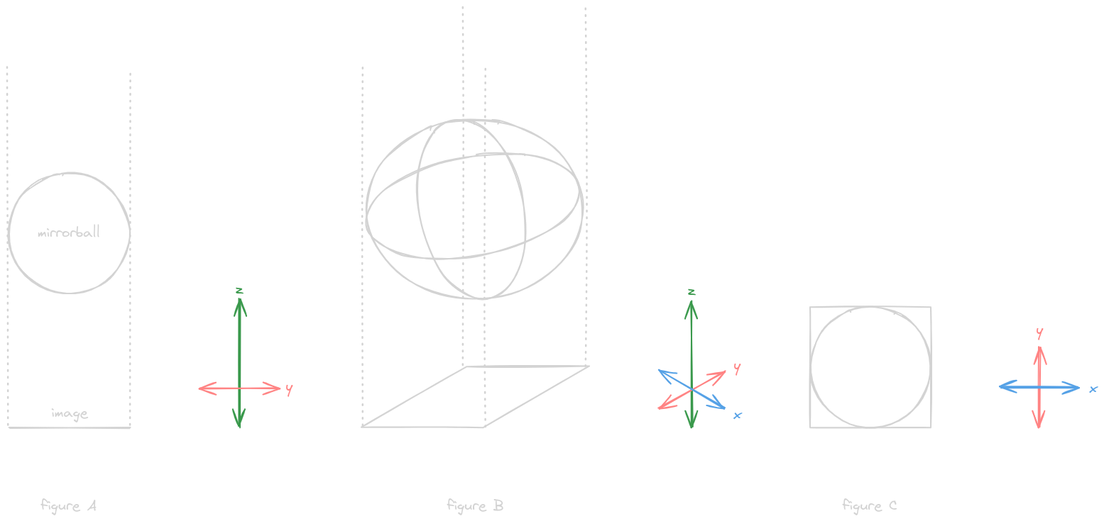
We begin by defining a sphere, the mirrorball, and a 2D plane, the image
In figure A, it is represented as viewed along the x-axis or, equivalently, projected onto the zy-plane
To clarify the 3D shape figure A is drawn to represent, figure B attempts to draw the figure as a wire-frame viewed from an angle that doesn’t align with any single coordinate axis
To further clarify the purpose of the dotted lines in both figures A and B, figure C shows a view along the z-axis or, equivalently, projected onto the xy-plane
Each figure is accompanied by a key to its visible coordinate axes, with the axis label in the positive direction.
The mirrorball is a unit sphere, centered at the origin
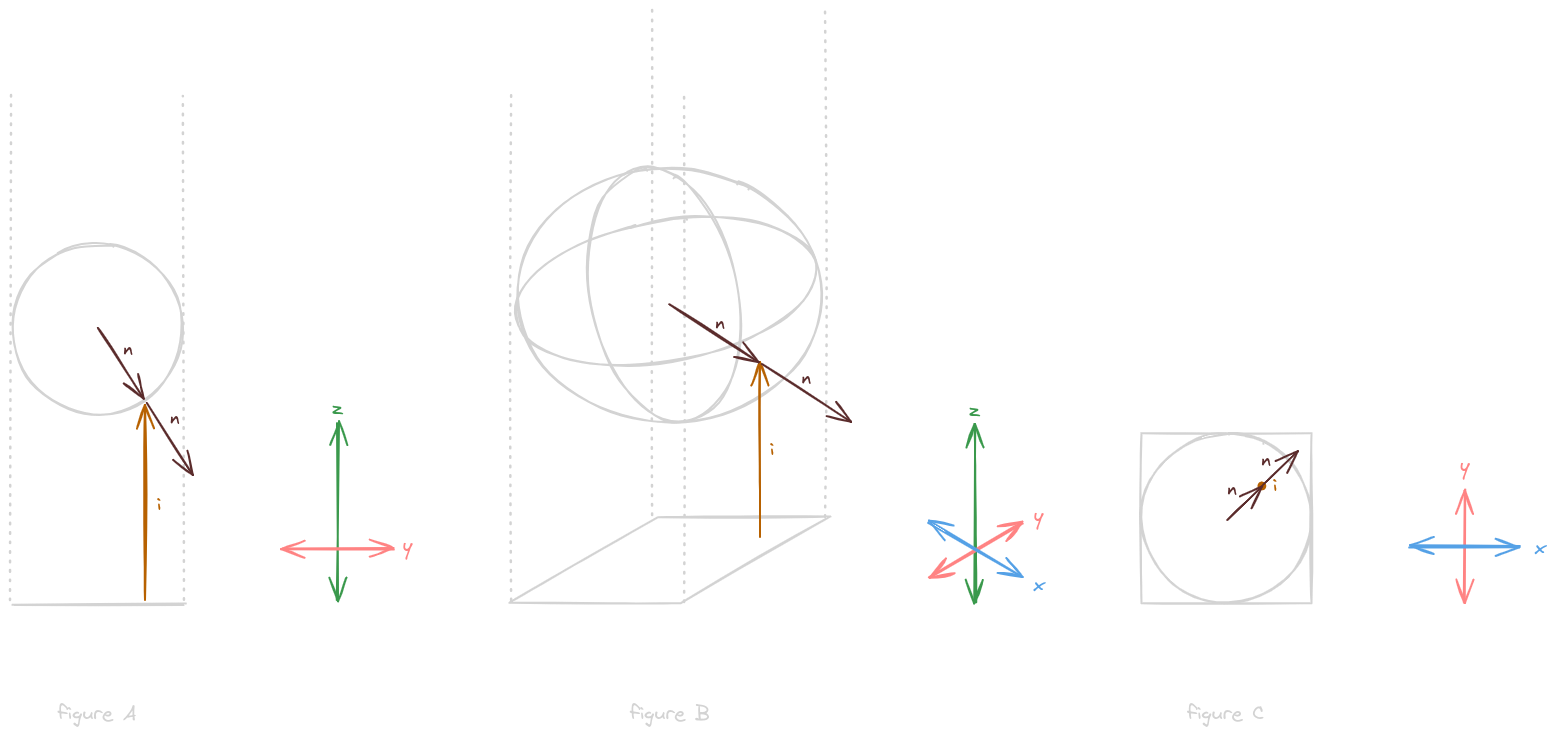
To begin, we’ll add a camera, defined by the vector i
Vector i defines our orthogonal camera, meaning that it points directly along the z-axis (equivalently, its x- and y-components are zero)
Next, we’ll consider the normal vector n, which defines the orthogonal unit vector at a point on the sphere or, equivalently, the vector from the center of the sphere to its surface at the same point
Normal vector n is depicted twice in each figure to convey these dual interpretations
Note that the x- and y-components of the normal vector n correspond to x- and y-coordinates on the image plane
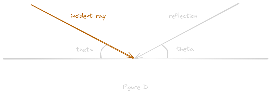
The law of reflection states that when a light ray strikes a smooth surface, the angle of reflection is equal to the angle of incidence, as depicted in figure D with a flat reflective surface
The formula for the law of reflection defines a reflection vector r as r = 2(i * n)n - i, where * represents the dot product
The dot product between two normalized vectors is equal to the cosine of the angle between them, so it is 1 when they point in the same direction, -1 when they point in opposite directions, and 0 when they are orthogonal
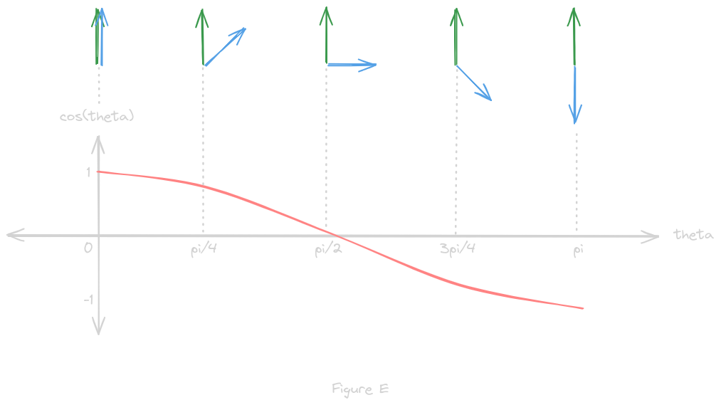
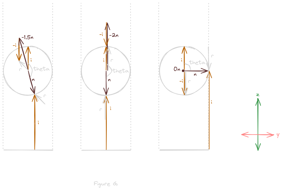
The camera vector i can also be drawn as a unit vector at the origin and center of the mirrorball, as in figure F
Now, it should the value of the dot product, which is also the cosine of angle theta, more clear visually
As depicted it is clearly a negative number between 0 and 1
If it is less than -1/2, meaning that theta is larger than 135 degrees or 3pi/4 radians, then the term 2(i * n) will be greater than 1
Thus, the combined term 2(i * n)n will represent the normal vector n scaled either up or down depending on theta, in this case it will amount to roughly -n
So the reflection vector r, in this case, will be roughly -n + -i
Translating reflection vector r, so that it points to normal vector n, it now visually depicts the angle light would take to reach the image
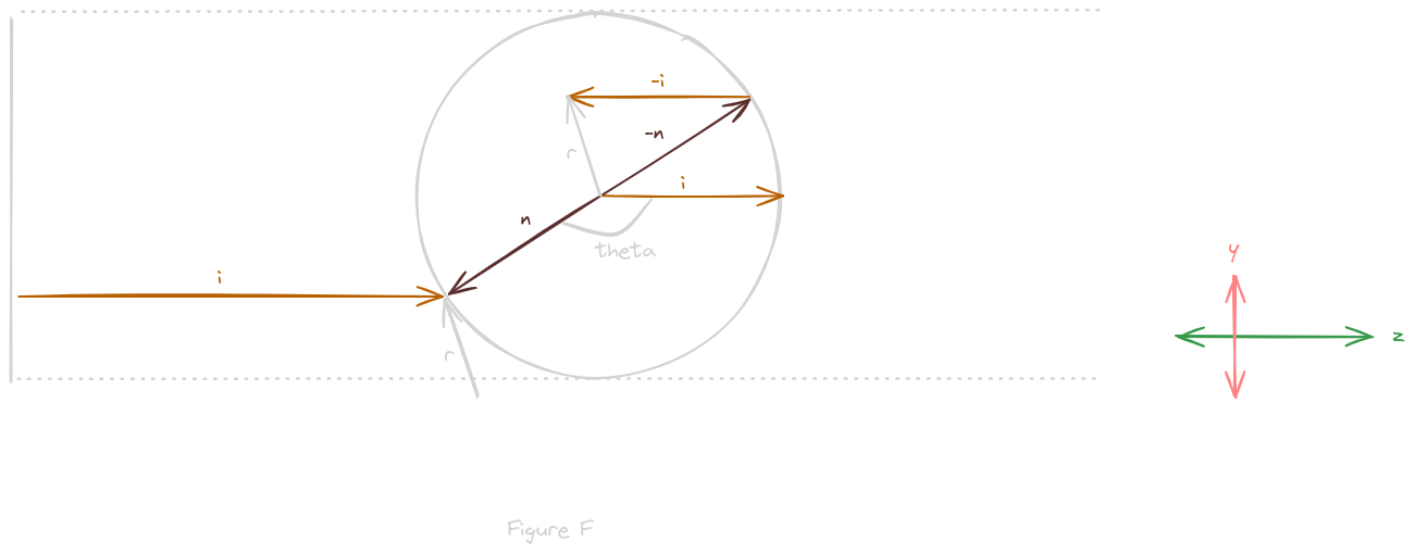
Figure G depicts an additional example and the two edge cases of the visual calculation of reflection vector r
So the reflection vector r shows us the direction of the path traveled by light rays captured by our camera at a particular point on the mirrorball
The Mirrorball Projection Term
The point of all this is to use our understanding of the mirrorball geometry and the law of reflection to calculate the colors of pixels in the 2D image, based on a reflection vector r
As Frost Kiwi states in his video on the subject:
“3D vector in. 2D vector out.”
The ultimate goal is to use the information contained on the surface of the mirrorball to look, as if from within the mirrorball, in some direction
Each reflection vector r represents a ray of light traveling from some point out in 3D space to the surface of the mirrorball such that it reflects in a direction perfectly aligned with our “orthographic” camera
So consider a reflection vector r and all of the various points on our mirrorball that r, which merely represents a direction and not a unique position, could touch
Out of all such points, the incident ray of light is only reflected directly toward the camera, parallel to the z-axis, at exactly one point on the surface of the mirrorball
Thus, the pixel in our mirrorball image at point p* has the color we would see, from the perspective of the mirrorball, in the direction r, if the mirrorball were infinitely small
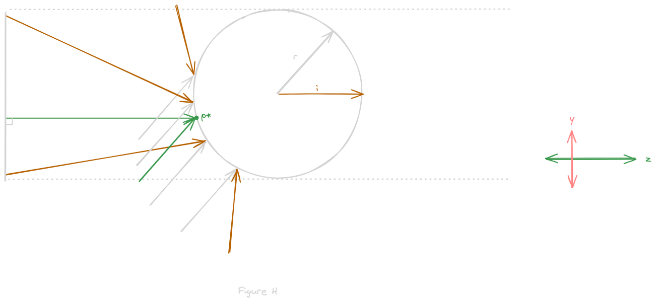
Figure F represents the formula for the law of reflection in 3D vector notation, filling in our known values for for i
Importantly, because our goal is to map the 3D reflection vector to a 2D pixel coordinate in our image, so that we can color it, we need to include image coordinates
Thus, using our insight from figure C, we can replace x- and y- values in the normal vector n with our desired image coordinates
To simplify, we can solve the dot product by multiplying each element pairwise and summing the result to get only the z-component of n
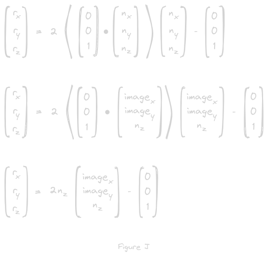
(note I skipped figure “I” on accident but it is too late now)
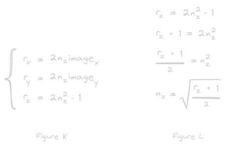
Drawing from Wladislav Artsimovich’s paper, “Improved Mirror Ball Projection for More Accurate Merging of Multiple Camera Outputs and Process Monitoring,” we can rewrite this as a system of equations, as in figure K
With a bit of algebra, we can isolate the z-component of the normal vector n, as in Figure L, allowing us to make a substitution to remove n from the problem altogether
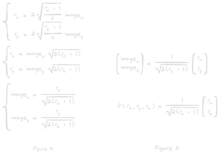
The substitution simplifies our system of equations, as shown in figure M, allowing us to isolate our image coordinates and yielding a simple function of the reflection vector r for each pixel in our image
This can be rewritten in matrix notation, as in figure N, to yield a function which projects the 3D reflection vector r onto a 2D vector representing a coordinate on our image
Now, for any direction in 3D from the perspective of the mirrorball, we know exactly where on the mirroball image to find the corresponding color
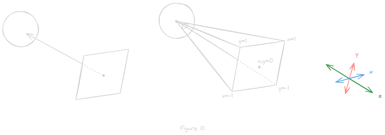
Next is to take a given direction, and, rather than finding a single pixel in that direction, find all the points a camera would capture if aimed in that direction, as described in figure O
Given a view direction, defined by a reflection vector r, we automatically get a unique 2D plane in 3D that r is normal to
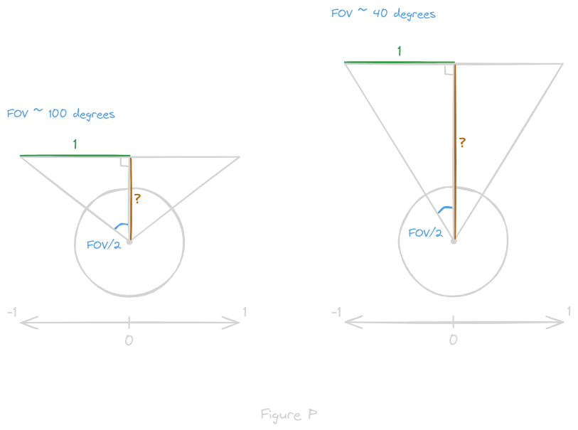
We can define a viewing rectangle as all points within some x- and y-distance in the plane’s coordinate system, as in figure P, then find the vector from each point on the rectangle to the center of the mirrorball
Thus, we have x- and y-components for every such vector r, but the z-component is determined by the field of vision (FOV) of our imaginary camera
The z-value is the same for every point, because the plane is parallel to the tangent plane of the sphere, and equal to -1/tan(FOV/2), as depicted in figure P
The negative sign simply comes from the fact that the reflection vector is defined as pointing towards the center of the sphere
By dividing the rectangle into pixels, we can compute the vector corresponding to each pixel:
[ 2 * x/width - 1, 2 * y/height - 1, and -1/tan(FOV/2) ]
Once we have a vector for every pixel on our rectangle, we can normalize and feed it into the mirrorball projection formula in figure N to find the corresponding location in our 2D mirrorball image
The mirrorball projection produces x- and y-values between -1 and 1, so we perform the opposite transformation as before, this time with the height and width of the mirrorball image, to compute the pixel location:
[ width * (x + 1)/2, height * (y + 1)/2 ]
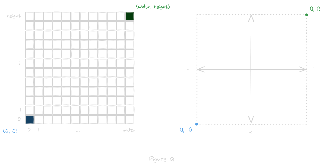
So every pixel in the image taken by our imaginary camera uses the mirrorball projection to find a pixel in our original image to use as its color
The image below shows an example of the “relevant portion” of the mirrorball needed to recreate a single view
Each blue dot corresponds to a point where the reflection and incident rays reflect off the surface of the mirrorball, such that the incident ray intersects the image plane defined by our real camera (left), and the reflection ray intersects the image plane defined by our imaginary camera (right)

